
metalworkingmag.com
21
'20
Written on Modified on
Renishaw News
Floating steel encoder scales for SMT
Position encoders with linear scales have wide-ranging applications in front-end and back-end semiconductor manufacturing processes. This application note discusses surface mount technology (SMT) applications and presents an example of where linear steel scale (installed to be thermally independent of its mounting substrate) may be preferable to the currently widely used, but expensive, near-zero thermal expansion scales.
What is an encoder?
A linear encoder consists of a position measurement readhead paired with a scale (an accurately marked ruler). The readhead measures position by directly sensing the regularly-spaced scale markings and outputs this information as an analogue or digital signal. The signal is subsequently converted into a position reading by a digital readout (DRO) or motion controller. Linear encoder scales may be long and are sensitive to thermal changes.
Encoders and thermal behaviour
The thermal behaviour of encoder scales is an important consideration when selecting any encoder system. Renishaw's encoder scales are predominantly either thermally independent of the substrate mounting surface (floating) or thermally dependent on the substrate (mastered).
Floating scale types expand and contract with approximately the same coefficient of thermal expansion (CTE) as the scale material and have a known CTE, which can enable the effective use of active scale temperature compensation.
Surface Mount Technology (SMT)
SMT machines pick up electronic components (such as passives, flip-chips and Quad-Flat packages) and place them in a given location on a printed circuit board (PCB) prior to reflow soldering. A PCB board is a multi-layer laminate with an in-plane (x-y) CTE of typically between 6 and 14 ppm/K, depending on the application requirements. Precise placement to within tens of microns is essential to ensure that the components make good electrical contact with the PCB.
A typical SMT machine comprises: a conveyor for PCB transfer, a gantry X-axis mounted on two parallel motor-driven rails (Y-axis), a pick-and-place head module and an automatic component feeder system. The head module has many individual suction nozzles for gripping components and is mounted on a leadscrew-driven carriage that moves horizontally along the gantry, as shown in Figure 2.
Each nozzle can move up or down (Z-axis) and rotate in the plane of the PCB to correctly orientate each component prior to placement. Vision systems are used to verify that each component has the correct rotation angle.
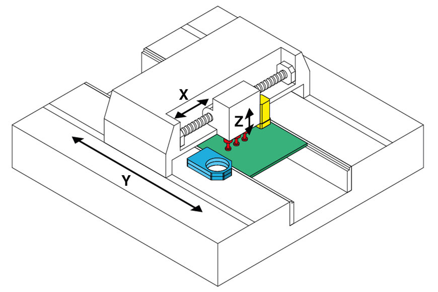
Figure 2: SMT machine showing a leadscrew-driven head module with suction nozzles (red), component camera (blue), fiducial camera (yellow) and PCB panel (green).
However, the high-speed placement operation is performed using only the pre-determined component position coordinates on the PCB and the relevant coordinate transformations between the machine frame, PCB frame and camera frames.
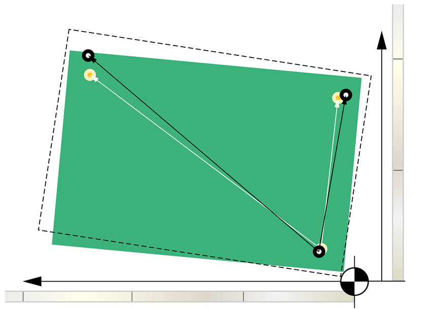
When a PCB enters an SMT machine, it contacts a board stop which also acts as the machine datum. Once the board is at rest, it is clamped in place. Before starting the pick-and-place procedure, two or three fiducials on the corners of each PCB are traditionally used to determine the board orientation, position, and linear expansion or contraction.
Linear encoders are mounted on X and Y axes to provide accurate position feedback to the machine controller.
Application example
Consider a steel-frame SMT machine that is located inside a factory with an ambient air temperature that rises by 5 ºC during a production run.
The machine has a 2 m long X-axis and a 3 m long Y-axis (longitudinal axis). Surface-mount device (SMD) components are mounted on a standard PCB panel with dimensions of 610 mm x 457 mm (24” x 18”). Three corners are marked with global fiducials to correct for panel offsets and provide a (0,0) datum point.
In this case, a floating linear scale is chosen for precision measurements and mounted on the machine's axes. These scales have a known CTE and can be thermally compensated using a temperature sensor, such as a thermocouple, fixed to the scale. Each encoder scale has a fixed datum position that corresponds to the machine datum, as shown in Figure 1.
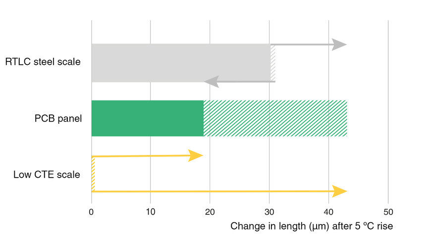
Figure 3: Comparison of the change in length of different materials, each initially 610 mm (24”) long, after an ambient temperature rise of 5 ºC (assuming thermal equilibrium). RTLC scale thermal behaviour is much closer to that of the PCB panel and the hatched areas indicate the range of values possible for each material.
The thermal behaviour of the PCB material is such that the PCB temperature follows, and is approximately equal to, the scale temperature, assuming thermal equilibrium with the air. The absence of phase lag between temperature vs. time plots of the scale and PCB enables scaling factor compensation of the linear thermal expansion of the PCB. Consequently, the difference in thermal expansion between the encoder scale and the PCB is proportional to the difference in CTE between the scale material and PCB laminate.
As shown in Figure 3, high placement precision can be achieved with little or no thermal compensation because the CTE mismatch between the steel scale and PCB material is reduced. This minimises the impact of error in the measured scale temperature.
For instance, Renishaw's RTLC scale is a stainless steel tape scale with a CTE of 10 ppm, which sits in the middle of the typical CTE range of PCBs.
A PCB with an X-Y CTE of 10 ppm would be thermally compensated by the linear expansion of the scale, enabling high precision pick-and-place operations that only need to account for board rotation and translation offsets. Another PCB with a higher CTE of 14 ppm would still be largely compensated by the scale expansion. A small mismatch in CTE between the scale and PCB helps to minimise errors when applying active thermal compensation.
Floating steel scales that expand at approximately the same rate as the PCB panel should enable significantly better placement accuracy and precision than that achieved with expensive, low CTE scales.
www.renishaw.com